Day 3

Introduction to Zbrush Digital Tutors

Setting up reference images

– These steps are specific to this model:

– draw a cylinder primitive

-in the Initialize palette set X and Y size to 20

– in the Deformation palette rotate by 90 degrees in the X axis

– subdivide several time

– Make PolyMesh3D

Preparing the start of the model.

Preparing the start of the model.

– under the Draw Menu there is a palette specifically for grids and reference maps. Options include which faces to assign Maps to (Front-Back, Left-Right, Up-Down), and an option for using one Map for both planes (one).

buttons for assigning reference images to different planes around the model.

buttons for assigning reference images to different planes around the model.

– Map1 / Map2 brings up the texture palette to select an image.

– If the image you wish to use isn’t in the texture palette, go to Texture > Import and the images will be available next time you click on Map1 / Map2. Other options are enabled once a Map is loaded.

"Use

Once an image is imported it can be applied to any of the reference map buttons.

Once an image is imported it can be applied to any of the reference map buttons.

– Draw > Snap > Snap to Mesh snaps the reference map to the size of the mesh on the canvas.

Snap to Mesh makes the reference image the size of the mesh on the canvas.

Snap to Mesh makes the reference image the size of the mesh on the canvas.

– Draw > (F-B/U-D/L-R) > Adjust allows for changing the reference map’s colour, contrast and cropping.

reference maps can be cropped and adjusted within Zbrush.

reference maps can be cropped and adjusted within Zbrush.

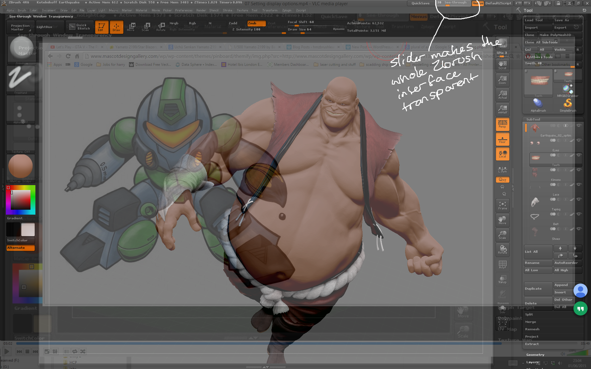
– To make the reference map visible through the mesh use Draw > Fill Mode 1 / 2 / 3, or the Front button.

Use the fill mode slider to change how visible the reference map is during sculpting.

Use the fill mode slider to change how visible the reference map is during sculpting.

– once reference maps have been set they can be all switched off at the same time using the floor button on the right shelf.

– Reference images can be created from a model using Draw > Snapshot to Grid, which creates a texture map for each of the six planes.

Use the Snapshot to Grid button to create reference images from a 3D model.

Use the Snapshot to Grid button to create reference images from a 3D model.

Day 2 Part 3

Introduction to Zbrush Digital Tutors

Setting display options.

– Draw includes several palettes relating to the canvas view.

The draw palettes lets you change viewport and floor settings.

The draw palettes lets you change viewport and floor settings.

– Transform > Transp makes every subtool except the active tool transparent.

Use the transparency button to make subtools except the active one transparent.

Use the transparency button to make subtools except the active one transparent.

– Transform > Ghost makes the transparent subtools more visible.

– Transform > Xpose (Shift + X) button explodes the model until pressed again, allowing you to see what subtools the model is made of.

Xpose explodes the model into its component  subtools.

Xpose explodes the model into its component subtools.

– some Tools eg Xpose feature a small X Y Z that can be turned on and off, affecting which axes the tool  works on.

– the Frame (F) button centres the canvas on the 3D model.

The frame button focuses the canvas on the model.

The frame button focuses the canvas on the model.

– the See Through slider makes the whole Zbrush interface transparent, allowing you to eg load up an image in a search engine that can be seen as reference while sculpting.

The Zbrush interface can be made transparent to see reference images on the desktop.

The Zbrush interface can be made transparent to see reference images on the desktop.