Introduction to Zbrush Digital Tutors
Using Panel Loops
– Panel Loops can be used in conjunction with Planes to create structured 3D geometry easily, eg teeth, capes, walls. A 2D plane is used to create the form with limited geometry then converted to a 3D solid.
– eg to create teeth: draw a plane3D then use the Initialize sliders to create the amount of geometry required for the model to be made.
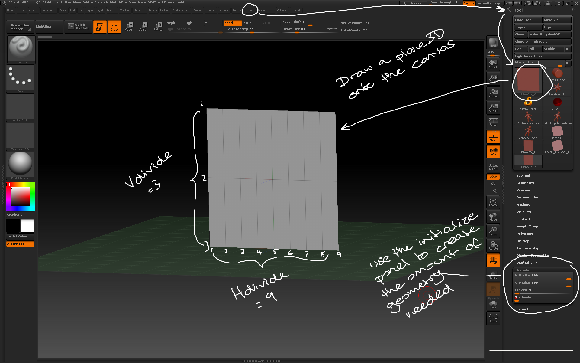
Use the plane3D tool and initialize sliders to create the base geometry for creating structured objects.
– Make PolyMesh3D then append the plane to the model it will be part of. Use the move brush to adjust the position of the geometry. Using as few polygons as possible will make the process easier.
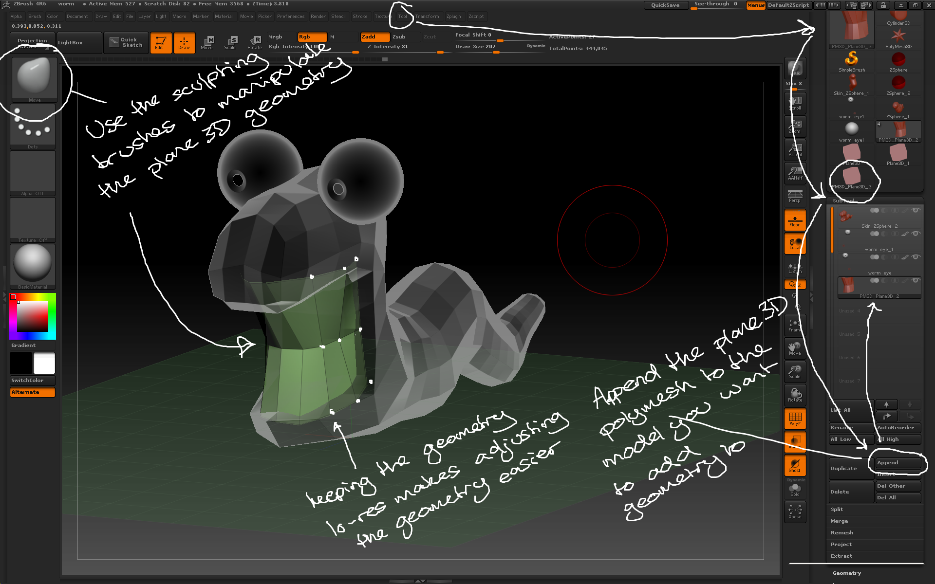
Append the plane3D to the model and use the sculpting tools to create the form.
– Once the geometry is positioned convert each polygon to a separate object; use the Tool > Polygroups > Group By Normals button with the MaxAngle slider set low then convert each polygon to a separate polygroup.
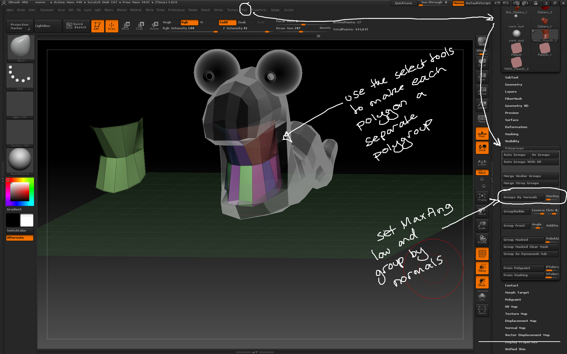
Use the group by normals button and the selection tools to separate each polygon into its own polygroup ready for separating.
– Use the Tool > Geometry > EdgeLoop > Panel Loops button to extrude 3D geometry from the plane with the following considerations:
– the Thickness slider determines how thick the 3D geometry is created
– the Polish slider determines how crisp the 3D geometry is
– the Double button extrudes the geometry in both directions
– the Loops slider determines how many loops of polygons there are in the new geometry
– the Bevel slider determines how bevelled the edges of the top and bottom of the new geometry are
– the Elevation slider determines where the origin of the extruded geometry starts, eg elevation = 0 extrudes the geometry equally from either side of the source polygon.
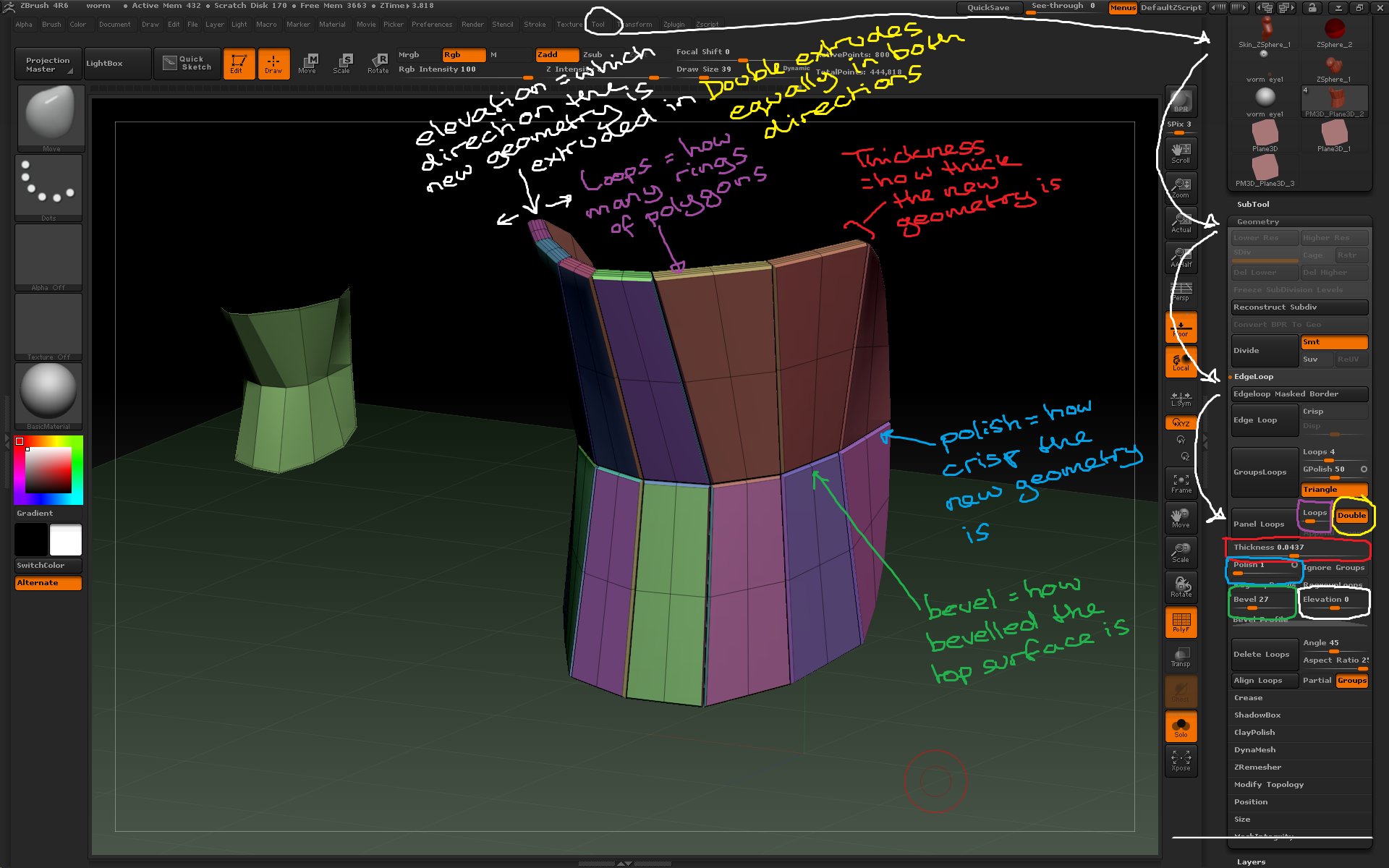
Use the different panel loop settings to vary how the new geometry is created from the source polygons.
– To modify each tooth individually, use the Tool > Polygroups > Auto Groups button to make each tooth a single polygroup, then use the Brush > Auto Masking > Mask By Polygroups slider set to 100 to ensure any actions only affect a single polygroup. This allows for individual sculpting while the teeth remain a single subtool.
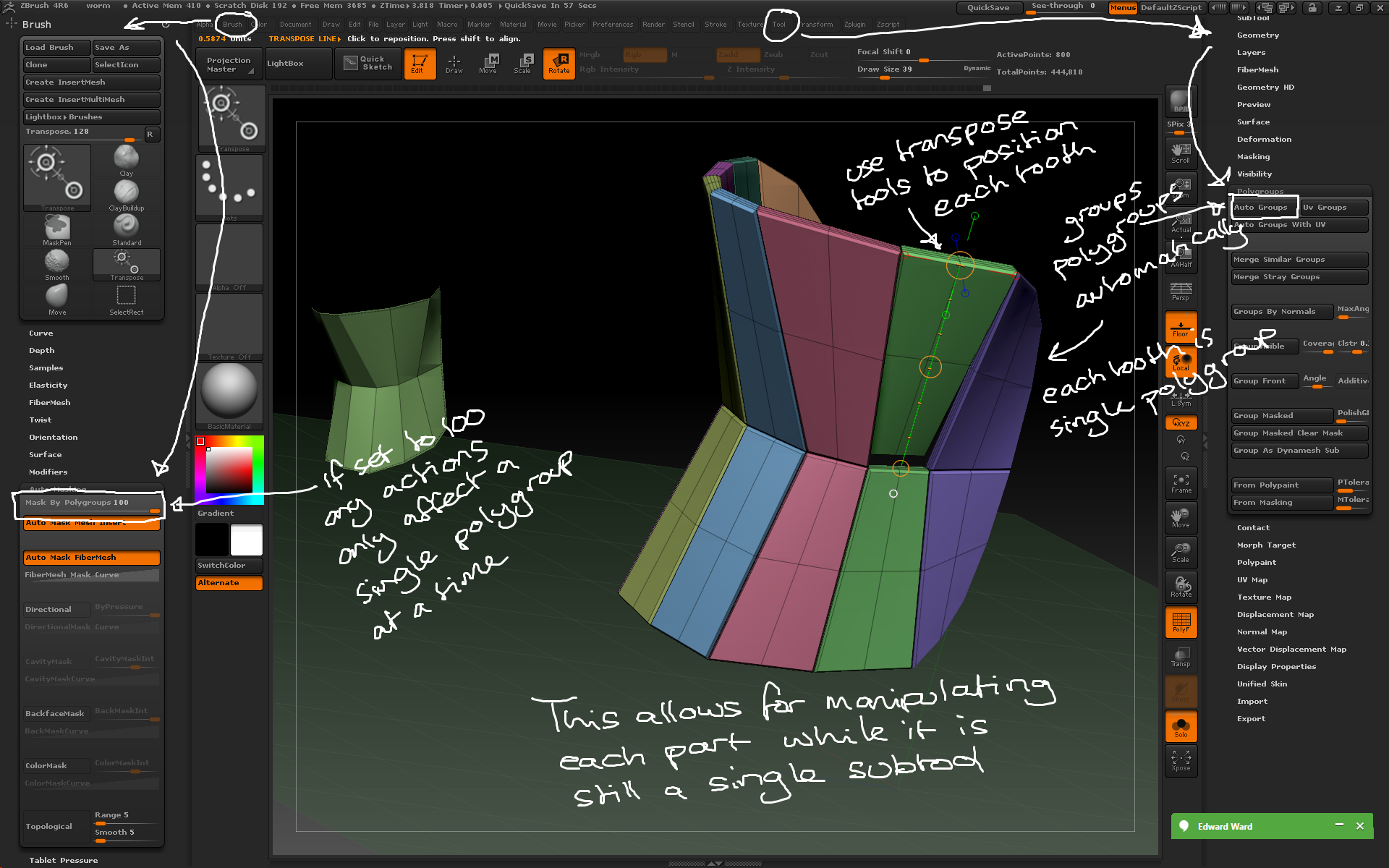
By grouping polygroups and using the auto masking slider you can manipulate individual parts of a model quickly without needing to mask parts.