Introduction to Zbrush Digital Tutors
Insert Mesh Techniques
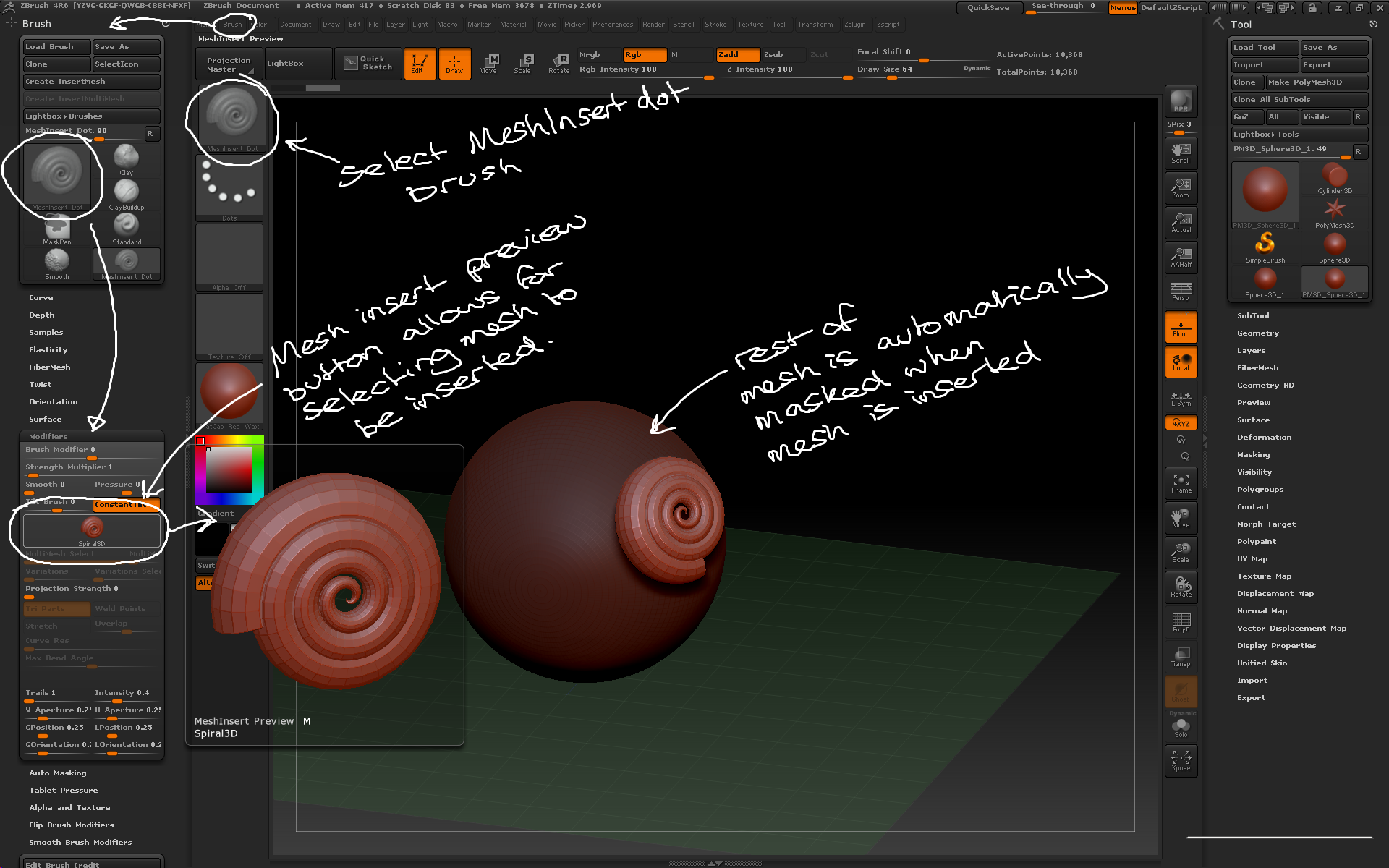
– The Insert Mesh brushes can be used to draw previously created geometry onto an active tool without automatically merging or creating new subtools.
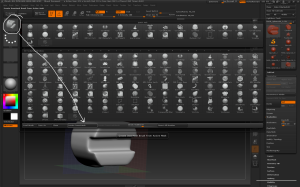
– Brush > MeshInsert Dot allows you to add mesh instances. To define which mesh go to Brush > Modifiers > MeshInsert Preview which brings up the tool palette to select a mesh from. Once a mesh has been selected it can be drawn on the surface of the model.
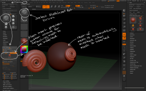
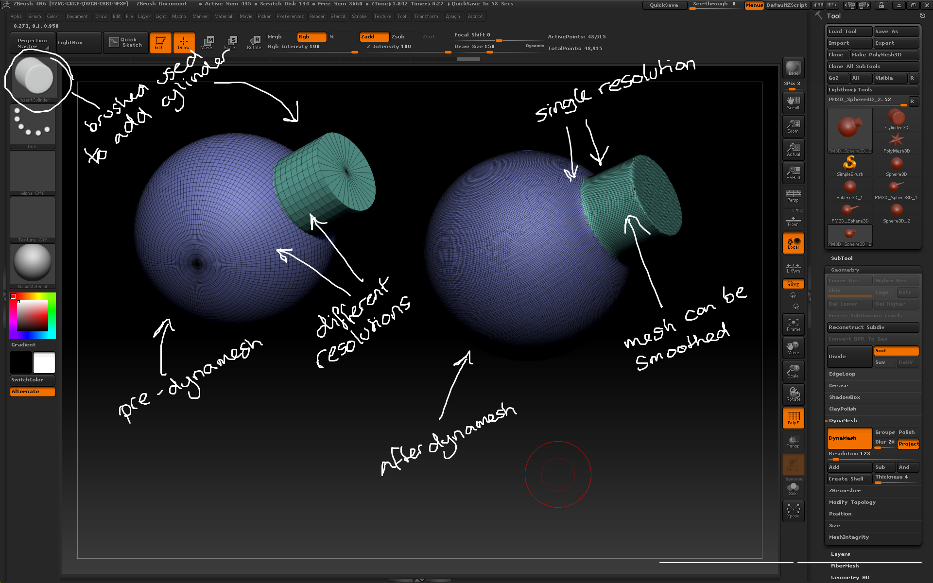
The InsertMesh Dot brush can be used to add new meshes to the tool once the mesh has been defined.
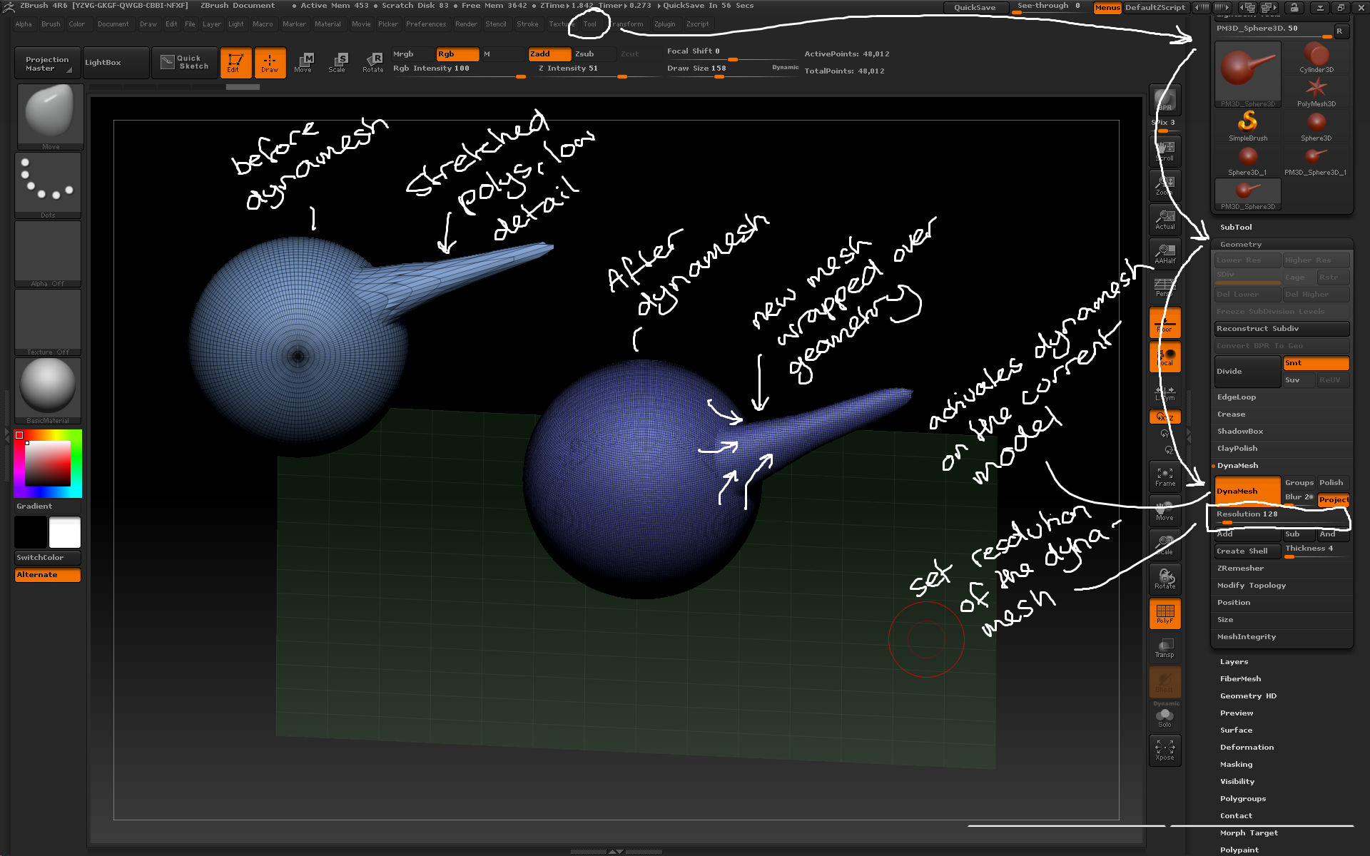
– When a new mesh is drawn, the rest of the model is automatically masked. This allows you to modify the inserted mesh like dynamesh, but the geometry will still be separate pieces.
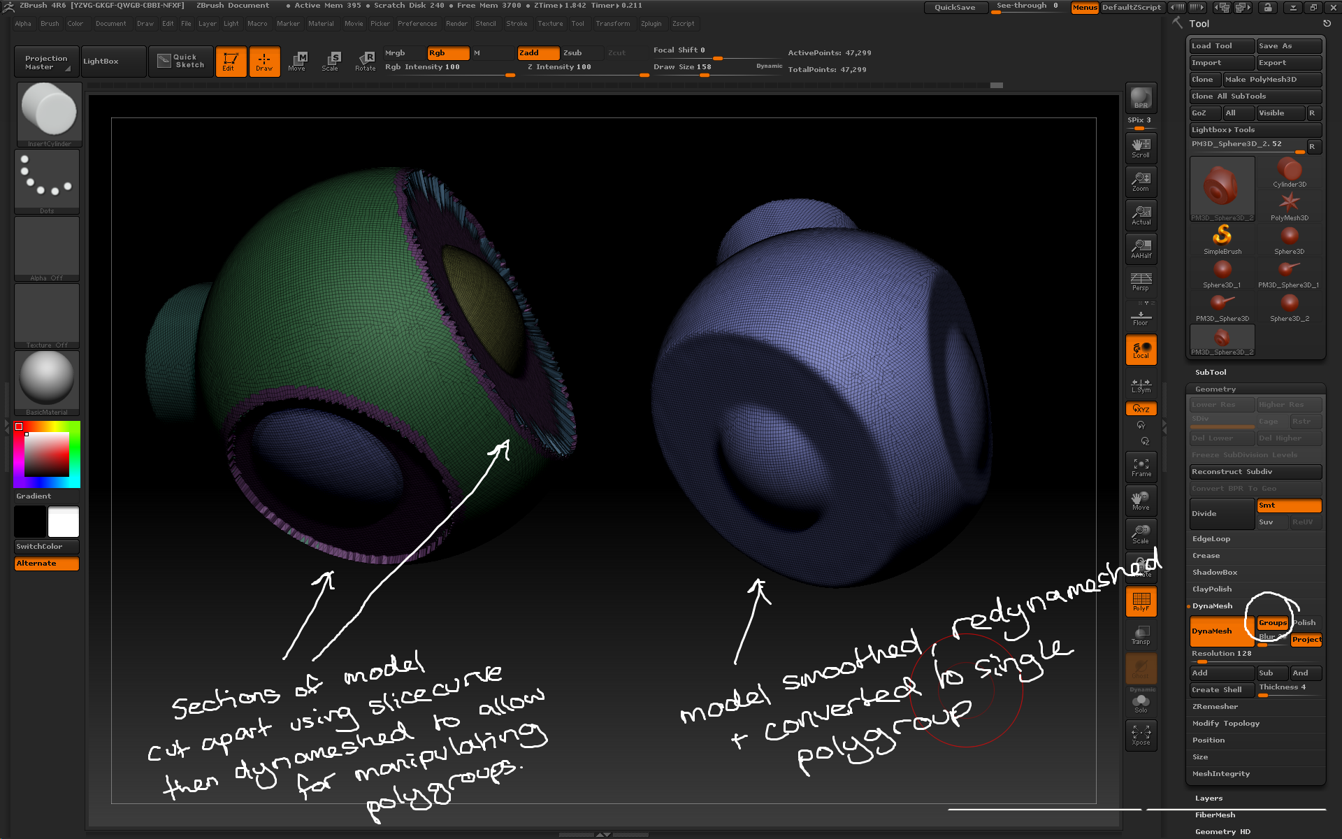
– The Tool > Subtool > Split commands can be used to separate out inserted meshes into their own subtools.
– Tool > Subtool > Split > Split to Similar Parts will split all the instances of the same mesh into a single subtool containing all the instances, even if they have been moved and rescaled.
– Tool > Subtool > Split > Split to Parts will split all the visible inserted meshes into individual subtools. Hide any subtools made of inserted meshes before performing this action to control how inserted meshes are grouped.
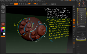
Inserted meshes can be split off into separate subtools using the split commands.
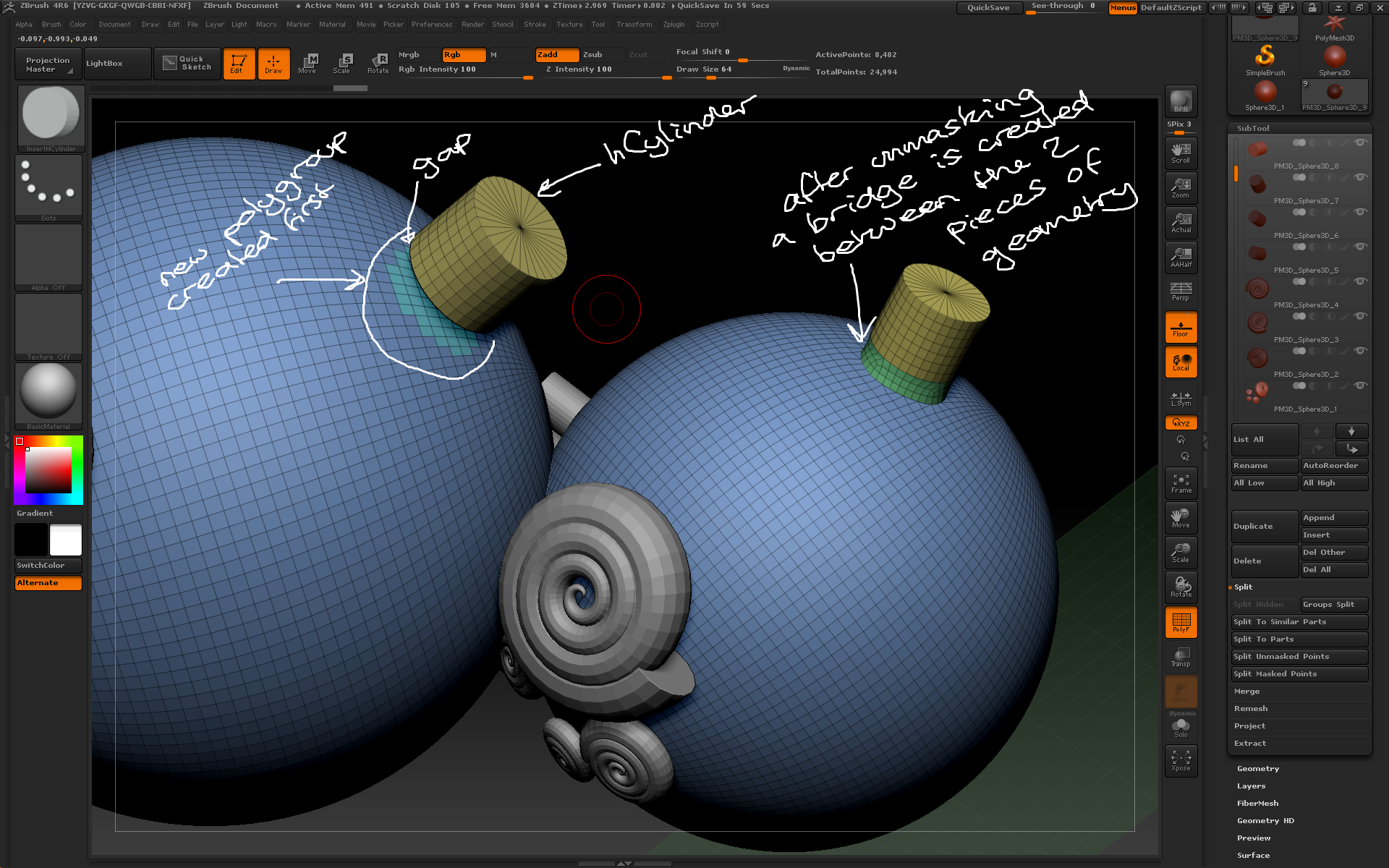
– Some InsertMesh brushes create open geometry which will leave a gap between it and the model. To make joins first create a new polygroup in that area, draw the new InsertMesh then unmask. New geometry will be created to bridge the gap. This is similar to dynamesh but without replacing the existing geometry.
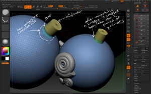
Open geometry can be added and bridged to the existing tool by first creating a new polygroup in that area then unmasking after adding the open geometry.
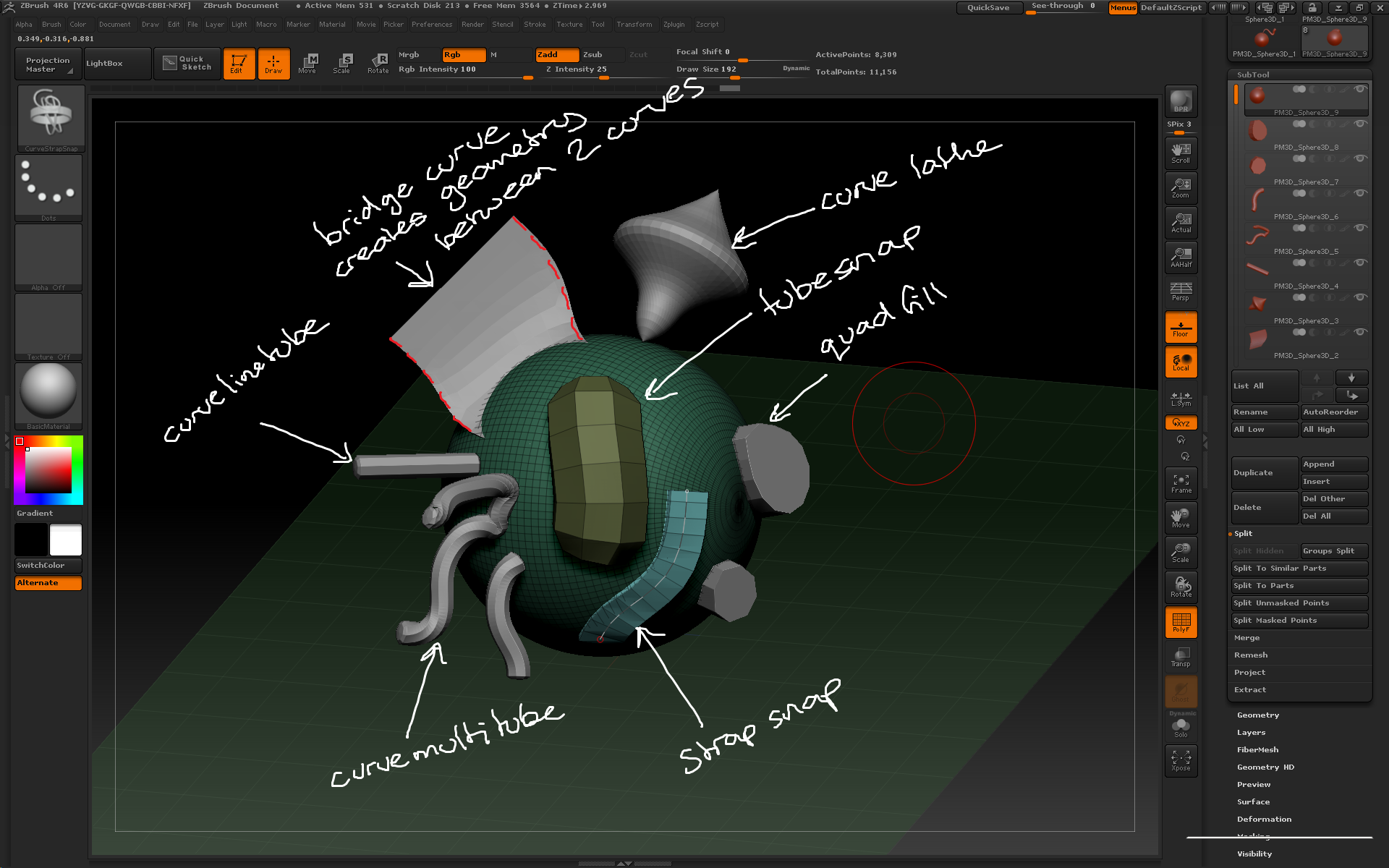
– Curve brushes can be used to create inserted meshes. CurveTube creates geometry along a defined curve that can then be manipulated.
– Stroke > Curve Modifiers contains options for changing how the curve creates geometry including tapering. Click on the manipulator ends to apply the effects.
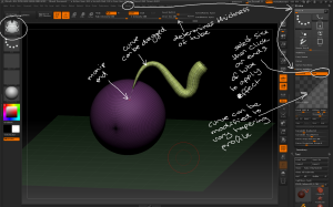
Curve tools can also be used to create inserted geometry.

Different curve tools can create different geometry.
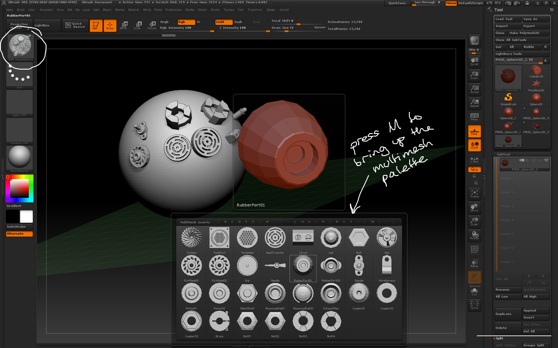
– InsertMultiMesh brushes combine several different meshes into a single brush. When using a MultiMesh brush press M to bring up the MultiMesh palette.

Multi Mesh brushes combine several different meshes into a single brush. The palette can be opened by pressing M.
– You can create new insertmesh brushes using Brush > Create InsertMesh. The active tool can then be a new insert mesh brush or appended to an existing multimesh brush.
Any tool can be turned into an InsertMesh brush in the brush palette.
– How deep in the tool the inserted mesh is drawn can be modified using Brush > Depth and moving the circle up and down.
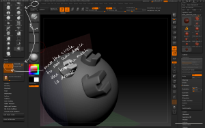
How deep in the tool the mesh is inserted can be modified using the depth setting
– X / Y / Z / Radial Symmetry can be used when using InsertMesh brushes to quickly add lots of detail across a model.