Day 9

Introduction to Zbrush Digital Tutors

Using Panel Loops

– Panel Loops can be used in conjunction with Planes to create structured 3D geometry easily, eg teeth, capes, walls. A 2D plane is used to create the form with limited geometry then converted to a 3D solid.

– eg to create teeth: draw a plane3D then use the Initialize sliders to create the amount of geometry required for the model to be made.
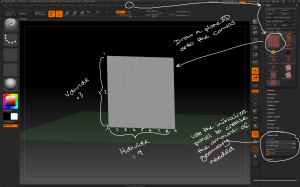
Use the plane3D tool and initialize sliders  to create the base geometry for creating structured objects.

Use the plane3D tool and initialize sliders to create the base geometry for creating structured objects.

Make PolyMesh3D then append the plane to the model it will be part of. Use the move brush to adjust the position of the geometry. Using as few polygons as possible will make the process easier.

Append the plane3D to the model and use the sculpting tools to create the form.

Append the plane3D to the model and use the sculpting tools to create the form.

– Once the geometry is positioned convert each polygon to a separate object; use the Tool > Polygroups > Group By Normals button with the MaxAngle slider set low then convert each polygon to a separate polygroup.
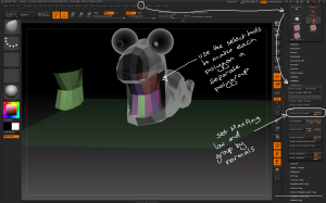
Use the group by normals button and the selection tools to separate each polygon into its own polygroup ready for separating.

Use the group by normals button and the selection tools to separate each polygon into its own polygroup ready for separating.

– Use the Tool > Geometry > EdgeLoop > Panel Loops button to extrude 3D geometry from the plane with the following considerations:

– the Thickness slider determines how thick the 3D geometry is created

– the Polish slider determines how crisp the 3D geometry is

– the Double button extrudes the geometry in both directions

– the Loops slider determines how many loops of polygons there are in the new geometry

– the Bevel slider determines how bevelled the edges of the top and bottom of the new geometry are

– the Elevation slider determines where the origin of the extruded geometry starts, eg elevation = 0 extrudes the geometry equally from either side of the source polygon.
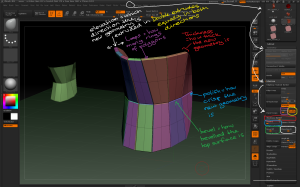
Use the different panel loop settings to vary how the new geometry is created from the source polygons.

Use the different panel loop settings to vary how the new geometry is created from the source polygons.

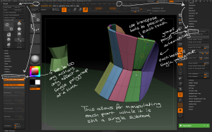
– To modify each tooth individually, use the Tool > Polygroups > Auto Groups button to make each tooth a single polygroup, then use the Brush > Auto Masking > Mask By Polygroups slider set to 100 to ensure any actions only affect a single polygroup. This allows for individual sculpting while the teeth remain a single subtool.
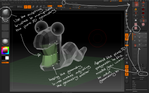
By grouping polygroups and using the auto masking slider you can manipulate individual parts of a model quickly without needing to mask parts.

By grouping polygroups and using the auto masking slider you can manipulate individual parts of a model quickly without needing to mask parts.

Day 3

Introduction to Zbrush Digital Tutors

Setting up reference images

– These steps are specific to this model:

– draw a cylinder primitive

-in the Initialize palette set X and Y size to 20

– in the Deformation palette rotate by 90 degrees in the X axis

– subdivide several time

– Make PolyMesh3D

Preparing the start of the model.

Preparing the start of the model.

– under the Draw Menu there is a palette specifically for grids and reference maps. Options include which faces to assign Maps to (Front-Back, Left-Right, Up-Down), and an option for using one Map for both planes (one).

buttons for assigning reference images to different planes around the model.

buttons for assigning reference images to different planes around the model.

– Map1 / Map2 brings up the texture palette to select an image.

– If the image you wish to use isn’t in the texture palette, go to Texture > Import and the images will be available next time you click on Map1 / Map2. Other options are enabled once a Map is loaded.

"Use

Once an image is imported it can be applied to any of the reference map buttons.

Once an image is imported it can be applied to any of the reference map buttons.

– Draw > Snap > Snap to Mesh snaps the reference map to the size of the mesh on the canvas.

Snap to Mesh makes the reference image the size of the mesh on the canvas.

Snap to Mesh makes the reference image the size of the mesh on the canvas.

– Draw > (F-B/U-D/L-R) > Adjust allows for changing the reference map’s colour, contrast and cropping.

reference maps can be cropped and adjusted within Zbrush.

reference maps can be cropped and adjusted within Zbrush.

– To make the reference map visible through the mesh use Draw > Fill Mode 1 / 2 / 3, or the Front button.

Use the fill mode slider to change how visible the reference map is during sculpting.

Use the fill mode slider to change how visible the reference map is during sculpting.

– once reference maps have been set they can be all switched off at the same time using the floor button on the right shelf.

– Reference images can be created from a model using Draw > Snapshot to Grid, which creates a texture map for each of the six planes.

Use the Snapshot to Grid button to create reference images from a 3D model.

Use the Snapshot to Grid button to create reference images from a 3D model.

Day 2

Introduction to Zbrush Digital Tutors

Basics of creating Geometry

– To view a wireframe on the mesh, tranform > PolyF or Shift + F or PolyF button on the right shelf.

Different ways to enable a polyframe

Different ways to enable a polyframe

Primitives can’t be sculpted but can be transformed while in edit mode. To see options go to tool > Initialize which will display options relating to that primitive eg initial size and resolution.

Initialize settings can be used to modify primitives before converting to polymesh for editing.

Initialize settings can be used to modify primitives before converting to polymesh for editing.

– Coverage is what angle the primitive is filled to in degrees.

– TaperTop and InnerRadius can turn a Cylinder into a hollowed flat cone.

– Twist can turn a Ring into a ribbed pipe.

– SweepProfile can create some interesting curves which are further modified in the Initialize palette.

Helix3D can be used to create eg suspension springs that vary along the length.

– Gear3D has a lot of options and can create very intricate shapes and features for other models.

– Lightbox (,) is where you can find imported tools, projects, materials, alphas and brushes.

– if a tutorial uses a non-standard sculpting brush it will likely be found in lightbox eg TrimHole.

Lightbox provides quick access to lots of important items.

Lightbox provides quick access to lots of important items.